Logic Gates
Logic Gates are building block that takes two binary inputs (0s & 1s), and produce a binary output. Each gate has its own set of rules, which is shown as a truth table.

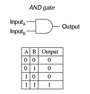
Figure 1: Logic Gates and their truth tables

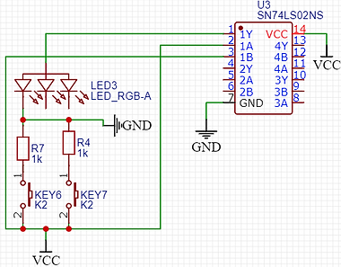
Figure 2: Experiment of Logic Gates
AND Gate
And gates are logic circuits that outputs high if two of the inputs are high, as shown in the truth table below. In this experiment, I'll be using a 3 input And gate IC (SN74LS11), which will be represented as push buttons that will light up the LED if all of the three inputs are high.

OR Gate
Or gates are logic circuit that outputs high if any of the inputs are high, or if both of the inputs are high as well, which is shown in the truth table below. In this experiment, I'll be using a 2 input Or gate IC, which is known as the SN74HC32N IC.


NOR Gate
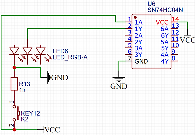
NOR Gates are logic gates that will only turn the output high if both of the inputs are low, in other words, NOR gates are inverse to OR gates. I'll be using the SN74HC02 IC, which is a dual input that consist of 4 NOR gates.

XOR Gate
XOR gates are logic gates where the output will be high if both of the inputs are different, if both inputs are exactly the same, then the output will be low. In this experiment, I'll be using the SN74HC86 XOR gate IC, which consists of 4 XOR gates and two input gates.


NAND Gate
NAND gates is the inverse of And gates, which means that the output will only be low if both inputs are high. In this experiment, I'll be using the SN74HC00N NAND gate IC, which consists of 4 NAND gate that has only two inputs.


Hex Inverter (NOT Gate)
NOT gates are one of the most simplest gate to use. Whatever is the input, the output will be an inverse of that. In this experiment, I'll be using the SN74LS04 IC, which consists of 6 NOT gates.